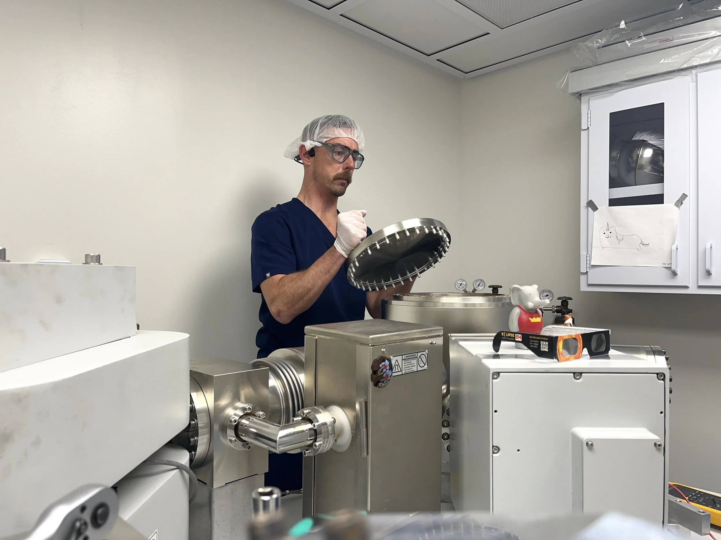
Removing the lid of the TIMS collector housing to acceses the Faraday cups. The backend of the instrument (flight tube and collector) is typically kept at pressures of < 5 x 10⁻⁹ mbar.
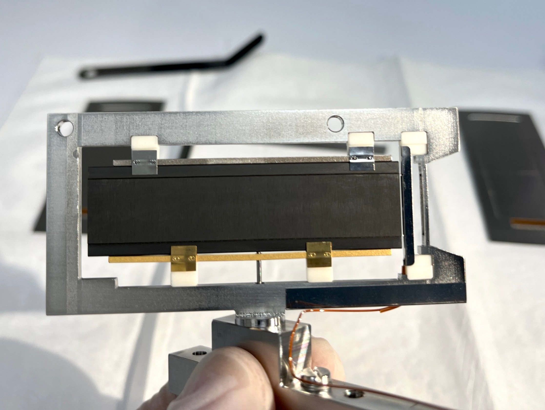
One of the movable Faraday cup assemblies with the side shields removed. In front of the graphite Faraday cup is the SE-plate which prevents the escape of secondary electrons
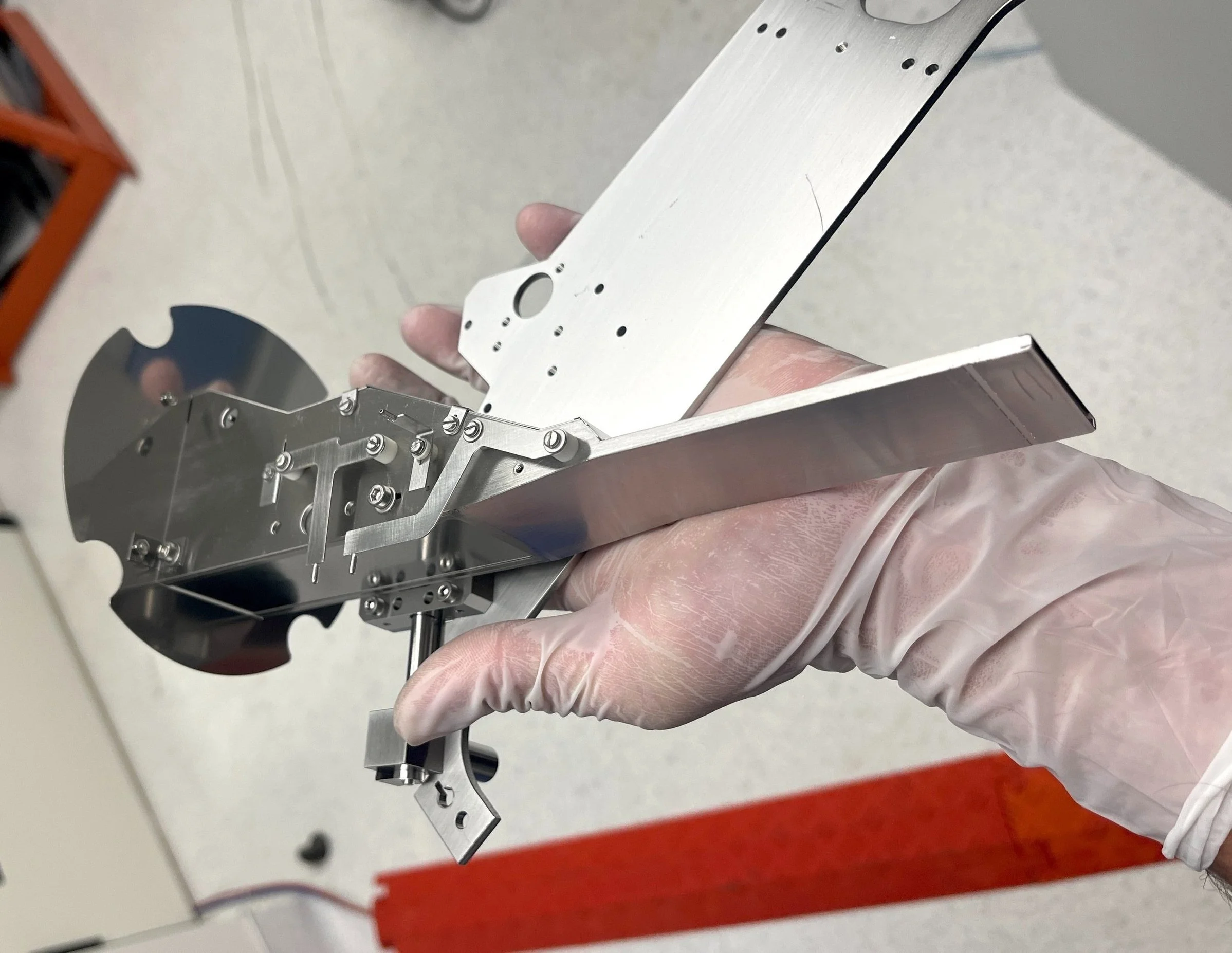
The center cup assembly. The Faraday cup is located at the bottom left. Also shown are the lenses which can redirect the beam into the secondary electron multiplier (SEM).
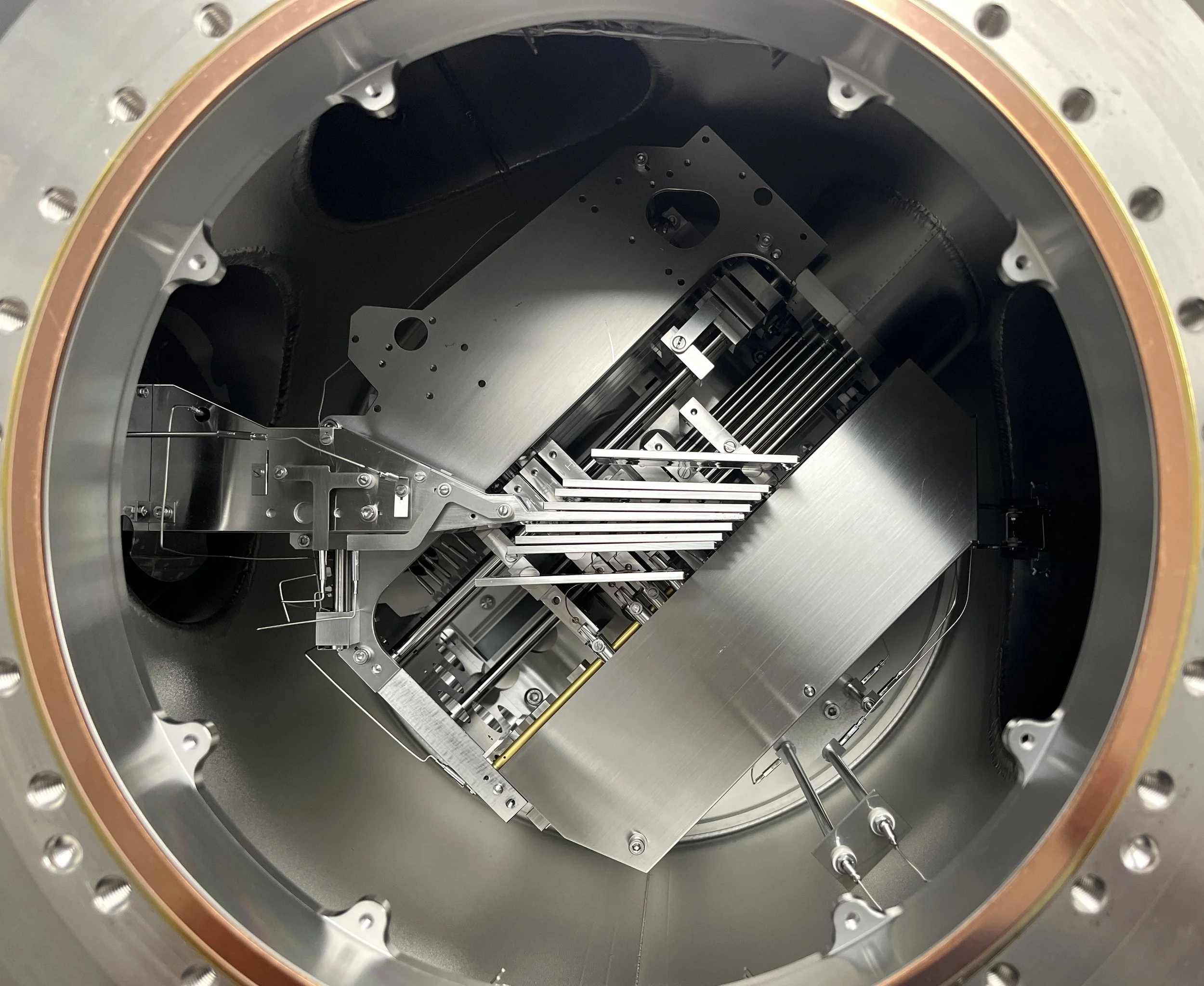
A birds-eye view of the inside of the collector housing. Visible are the eight movable Faraday cups and the fixed center cup/SEM assembly.
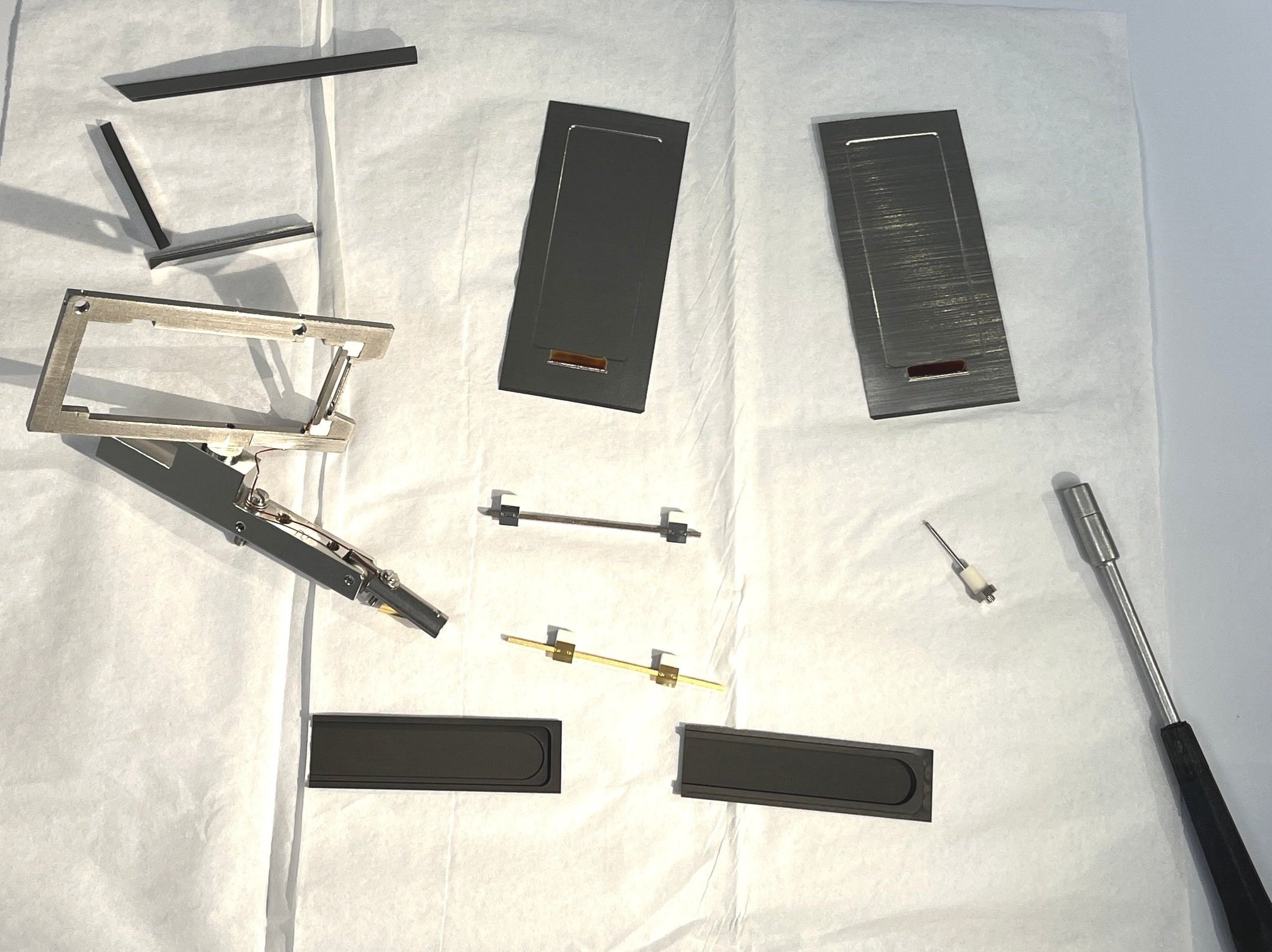
A fully disassembled Faraday cup assembly. Bottom row: the two halves of the graphite Faraday cup. Middle row: the Faraday cup frame, insulated support bars, signal pin. Upper row: side shields for cup frame
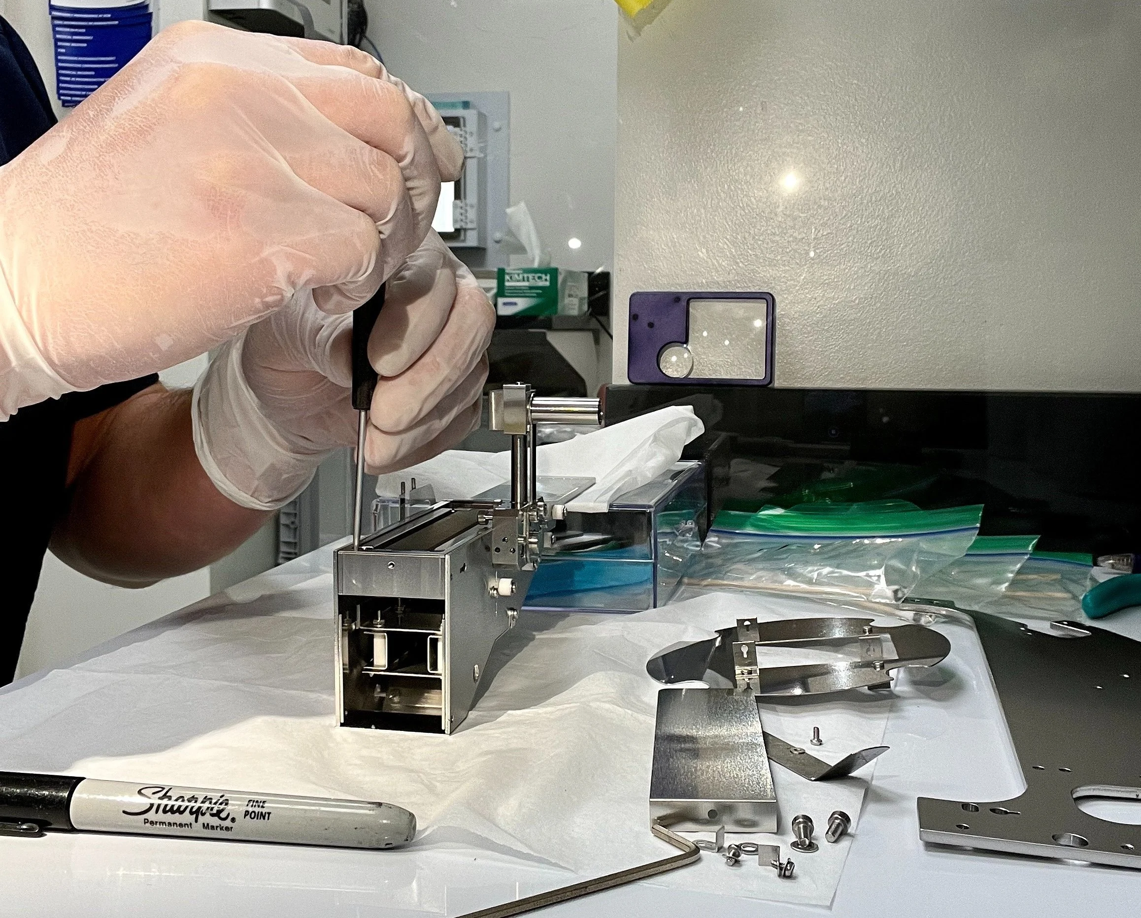
A partially disassembled center cup assembly. The graphite cup liner is exposed (right of screwdriver). Below this are the lenses for the beam guide (SEM not pictured).